
THE DESIGN & SPECIFICATION.
The Idea was to design and develop a 3D printer which is simple to build, easy to move around and travel with, built with simple materials and equally strong and precise.
Many open source designed 3D printer have inspired the design of TeeBotMax. Many thanks for sharing: to all the open source developers worldwide over.
Special thanks to – Josef Prusa (Prusa I3), Emmanuel Gilloz (FoldaRap), Richard Horne (Richrap), Reifsnyderb (J head Hotend) just to mention a few.
Files Links
Download PDF build manual and all 3d STL file via github…..
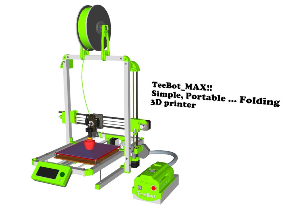
3D Rendering TeeBotMax Fully Assembled
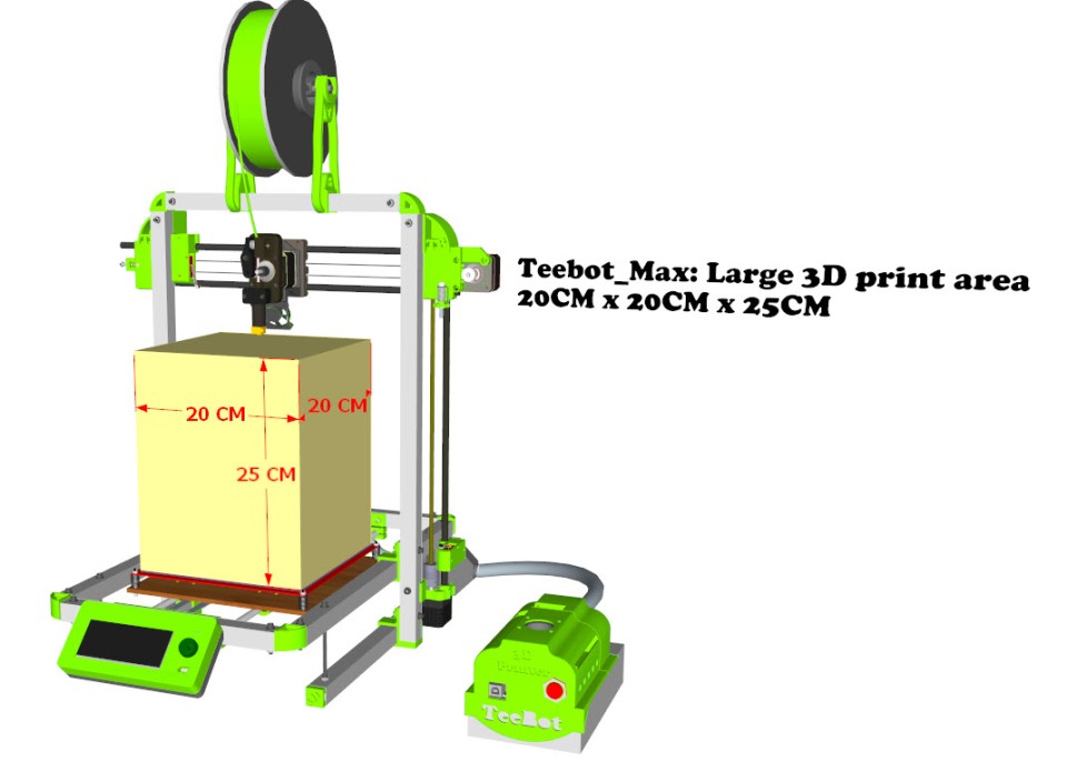
Print Area 20cm x 20cm x 25cm
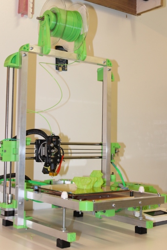
TeeBotMax fully constructed.

Z Axis motor mount

Frame joints

Corner pieace

Heated print bed.
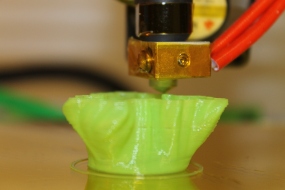
Printing…

Printing…

Julia Vase #011, thingiverse thing:126567

The wise owl

Scripted vases by hakalan, thingiverse thing:104694

Scripted vases by hakalan, thingiverse thing:104694

Julia Vases

Julia Vases

Close view

Close view

TeeBotMax folded down for easy storage & Transport
Tributes to owners of used models

Owl statue

Julia Vase

Scripted vases
Youtube Channel
Link to videos here
ABOUT THE MANUAL.
This manual provides you with a visual step by step guide on how to build or assemble TeeBotMax 3D printer. For a detailed step by step guide please use the build manual pdf, you will have to source the material/parts needed for your build according to the design.
Many will like to start with a complete/ partial kit, you can grab one here (www.3dstuffs.nl/)
Please report any error detected in this documentation.
I do all of my drawing in Sketchup and a big fan of the software.
Feel free to get in touch, if you have related questions, collaboration/business enquiry, or just simply talk 3D printing
Materials Needed
The manual contains a detail list of materials needed, there dimensions and where to source some. Here is a summary of materials you will need.
- TeeBot_Max Printed parts 1 set Download link above.
- 4 Meters of square aluminium pipes (2cmx2cm).
- Stepper Motors Nema 17 5 Pcs
- Reprap compatible electronics
- Mechanical (Smooth rods, bearings, belt pulley)
- Power supply (12volts with a min of 15A)
Printed Parts
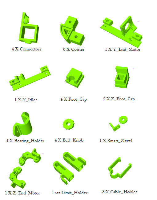
Printed Parts
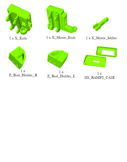
Printed Parts
SMOOTH & THREADED RODS.
2x Smooth rod Ø8 x 46Cm
4x Smooth rod Ø8 x 42Cm
2x Threaded rod M5 x 40Cm
ALUMINIUM FRAME.
The frame pipes are cut out of 2cm square tubing, 9 in total.
25cm x 2Pcs.
46cm x 2Pcs.
50cm x 2Pcs.
30cm x 1Pcs.
36cm x 2Pcs.
The build manual is divided into the following sections
Part 1 (Main frame)
Part 2 (Print platform)
Part 3 (Assembling the X Axis)
Part 4 (Assembling the Z Axis)
Part 5 (Extruder carriage & belt)
Part 6 (ELECTRONICS)
Part 1 (Main frame)
The PDF manual above gives a detail step by step approach to build the main frame after which the completed frame should look like this flipped upside down.

Main frame flipped upside down
Part 2 (Print platform)
The print platform consist of a wooden board, bed MK2 heat bed and a glass surface. The glass surface can be a clear glass or thick mirror, any size will work , but not thicker than 4mm. On completion of the part 2 the printer should look like this.

Print bed support.
Part 3 (X Axis)
The X axis is assembled by first installing one of the motors into the X motor end, and then installing the rods.

X Axis assembled
Part 4 (Z Axis)
The Z axis is completed by mounting the two 50cm Z axis pipes, installing the motors, threads and finally mounting the X axis in place.

Z axis, with X axis mounted.
Part 5 (Extruder carriage & belt)
Zip tie…. zip tie, zip tie…

Extruder mounted on carriage.

Extruder extension for large stepper motor
Behind.

Behind the X carriage
On completion of the mechanical build should look like this

The complete Mechanical build

Black and Red

Black and Red

Black and Red

Black and Red
TeeBotMax doing long hours print !!
Very impressive!! @ 6 hours 40min 82% of print done!!

Long hour Print

Hi Emmanuel,
I am just starting to build this nice printer.
My question is. Where can I find the STL files for the nice Controller box ?
Thanks
Joerg
Hi Joerg,
I am glad you are building it!!, thingiverse thing:35438.
Regards,
Emmanuel.
Hi Emmanuel,
Thanks for your answer, but I am searching the stl files for the controller box not for the LCD panel box.
Will you correct the STL files regarding the issue with the wrong holes soon !
Please see the comment on github for this issue:
nic0laz commented on 19 Aug
Hi, on the build manual the 25cm bar should have 2 holes spaced by 9cm, they are the anchor point for the y idler or y motor holder. Now, on the plastic piece those holes are 9.2cm appart.
Thanks
Joerg
Hi Joerg,
Ah ha.. Ramps casing has been uploaded, the wrong hole issue is in the documentation, the stl file remains the same :). The manual has since been updated. Note on the controller box, sits perfectly on power supply with 112mm width.
Regards
Emmanuel
Hi, I am in the process of building the Teebotmax ( As I found your documentation is the clear and a good one in internet for 3d printer making ! thanks for that) however now I have printed (with my other printer) the X_motor_iddler and X_End and I could not understand how did you insert the iddler in the X_End, so it can protrudes out to hold the bearing as per your photos. I am not able to understand how it entangles on the rectangular holes on the X_End. Because I am not able to make it entangle in the rectangular holes at all. Can you help me. Thanks in advance. If you can share me your email I can send you the photos of my problem.
Nice to know you building!! you have to cut the small bridge (2 plastics) then the idler will go in example here.
Send photos when you are complete and feel free to ask if you need more information.
Hi tutuemma, Yes I also had that hunch (cutting the small bridges) , I did it and Idler now goes in. Thanks, I am not proceeding further in building it. Can you help to me know how to post intermediate photos about the progress , so we can share the progress (if it is ok for you of course)
sorry I wrongly wrote “I am Not proceeding further ” typo mistake !, I am very much proceeding to build TeebotMax… working continuously to finish it…. will seek you for any help on the way.. thanks…
is there any problem if i increase the printing area to 400mmx400mmx400mm by some modification.will there be any problem??please reply asap.will vibration increase ??
I would worry about the height of 400mm, the width and breadth is no problem. Unless you intent to support the X gantry by fastening it to something solid, maybe a wall?
Hi Emmanuel,
I build this printer end I very setisfaction
please where I found STL files for extruder with Auto bedleveling/ Automatic Calibration becouse I order this parts
http://www.ebay.com/itm/281466581555?_trksid=p2060353.m2749.l2649&ssPageName=STRK%3AMEBIDX%3AIT
thanks in advance
Marijan
Hi Marijan
Good to know you built the printer!! The STl file for the Auto calibration will be available soon and announced here. I am currently working on making it universal to fit the all_metal hotend.
Regards
Emmanuel
Hi Emmanuel,
thanks for the prompt reply ,that’s good news, what is your experience with the hot end of which would you recommend, if I can use this model to your design
http://www.ebay.com/itm/121593695161?_trksid=p2060353.m2749.l2649&var=420555485780&ssPageName=STRK%3AMEBIDX%3AIT
, whether you may be thinking about the version with bowden cable extruder
thanks again
Regards
Marijan
HI Marijan,
I keep to direct drive extrusion since the printer is strong enough to carry the weight and more. To be honest just about any hotend will do!! Take your time to calibrate any hotend by starting slow. play with speed, temp and you will get the best out of any hotend. if the hotend comes assembled take it apart!! and reassemble it yourself, I have seen lots of loose/flimsy assembly of hotends.
Regards Emmanuel
What filament size can we use ? 1.75 mm or 3 mm ABS ?
HI Meena,
It is Compatible with both 1.75mm and 3mm PLA & ABS or any filament that prints below 240 degrees. My preference is 1.75mm, but your need might be different.
Do you have a specific application/use in mind?
Hey ,
Thanks for the early reply ! We basically want to use it for personalised gifts and toys . So which one should we opt for ? 1.75 mm or 3mm ?
Regards,
Meena
I guess 1.75mm will be your best choice. I find it easy to unwind from the coil/spool and you will need less effort to extrude it.
Also , I wanted to ask you whether the spring of the “Teestruder” is of some specific tension ?
Not, really anything that gives a good grip and fits. Here is the Specs of the one I normally use Outside diameter: 10mm
Inside diameter: 8mm
Total coils: 9
Length: 25mm
anything similar should be fine.
Hi , Phew ! completed building my teebot now ( I took your help earlier and you had helped me thanks), (all STL, FW, Mech parts followed from your GitHub repository )- using Repetier and Slic3r to print ), did a firstcube print (with PLA1.75mm).
But the print appears mushy (images shared below) – Can you help to give a pointer where to start debugging from. Thanks – BTW I am following your design web updates and you had taken it to an awesome level now good.
https://drive.google.com/file/d/0B2dLiyhOq0STLTVVdF9XMWxlSFk/view?usp=sharing
https://drive.google.com/file/d/0B2dLiyhOq0STRUlsQ2JZVVBCQ2s/view?usp=sharing
https://drive.google.com/file/d/0B2dLiyhOq0STNEhENTNHNHBrazA/view?usp=sharing
https://drive.google.com/file/d/0B2dLiyhOq0STWXVvNE5IQzlXYXM/view?usp=sharing
HI
Thank you!! I am glad you made it this far. I think you print too hot. But it is hard to really tell. if you make a video short one of about 30 seconds while the printer is printing it will help more in diagnosing the problem. Great yellow colors!!! I hope the Extruder is ABS?
Regards
Hi tutuemma ,
I found the basic problem in the Marlin firmware settings which I loaded ( in configuration.h ) file
somehow it was totally wrong for ext-ruder (it was madly pushing the filament)
#define DEFAULT_AXIS_STEPS_PER_UNIT
78,78,4002.769,515.91048
I changed it to after calculating the steps/unit of the extruder’s feeding
#define DEFAULT_AXIS_STEPS_PER_UNIT
78,78,4002.769,110.49
This link helped to arrive at the right number (https://www.matterhackers.com/articles/how-to-calibrate-your-extruder)
Now things have come into the control (somewhat !).
At least a decent shape is getting printed
as these photos and videos show
1.https://goo.gl/photos/NyEGALPpgiWKVxMb8
2.https://goo.gl/photos/JtxrZj9zacMtbuuC9
3.https://goo.gl/photos/YqGRALgWNmoMEW819
But I have still some challenges as below:
1.Not able to keep the ext-ruder carriage straight , means due to motor weight and the metal clamp which I made for holding the induction z sensor all put together it is sagging the whole assembly that the nozzle is not in 90deg with respect to bed ! I am sorting it out. Any idea on this , how to avoid sagging of the ext-ruder assembly. Because of this the ext-ruder nozzle plough on the former printed surface and ruins the print !
2. I am using repetier + slicr3 RAMPS 1.4 + Arduino Mega 2560 for my electronics
Do you use the same ? Which host program are you using , by any chance repetier+slicr3 – if yes can you share the config files which you use, for them.
(thanks I got those awesome yellow parts printed from my friends professional PLA based 3D printer to start building my printer (ho no your printer ! 😉 )
Mine is PLA – filament and no heated bed. Extruder is for PLA 1.75mm – (set at 200DegC and calibrated with external thermocouple). printbed is full flat aluminium sheet with spring loaded adjustment with painter’s tape.
Anyway thanks for the encouragement .. I am working on it ……….meanwhile if you can help on those questions.
Teebot rocks !
Hi !
I am having a weird problem . As soon as I give the print command from the laptop , the 12 V 20 A power supply goes off. What could be the reason for this ? We have followed the exact design as yours. Since I’m a beginner I’m not able to figure it out ! I’d really appreciate your help .
Thanks
Hi,
I see this print head uses 1 filament at a time, would you recommend the usage of a multi-filament extruder and if so how difficult will it be to set the programming up for it.
Hi there,
Building It QTEK The moment. ONE question: The 110mm screws are indicateur as M8. However In The pictures They seem to be smaller?.
Cheers ,
Andreas